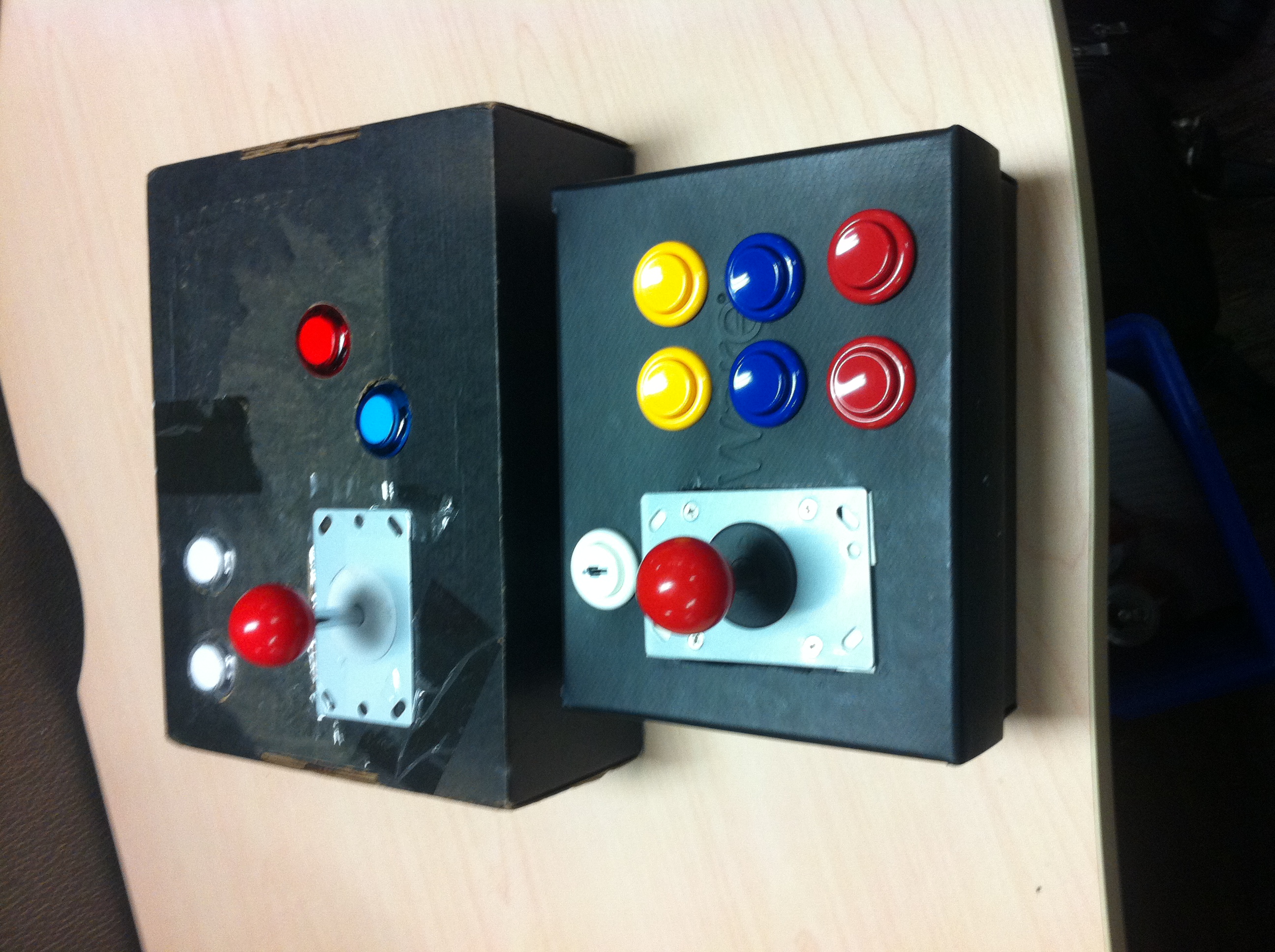
 Remember that ugly box from a few months back I made for playing classic Arcade games?
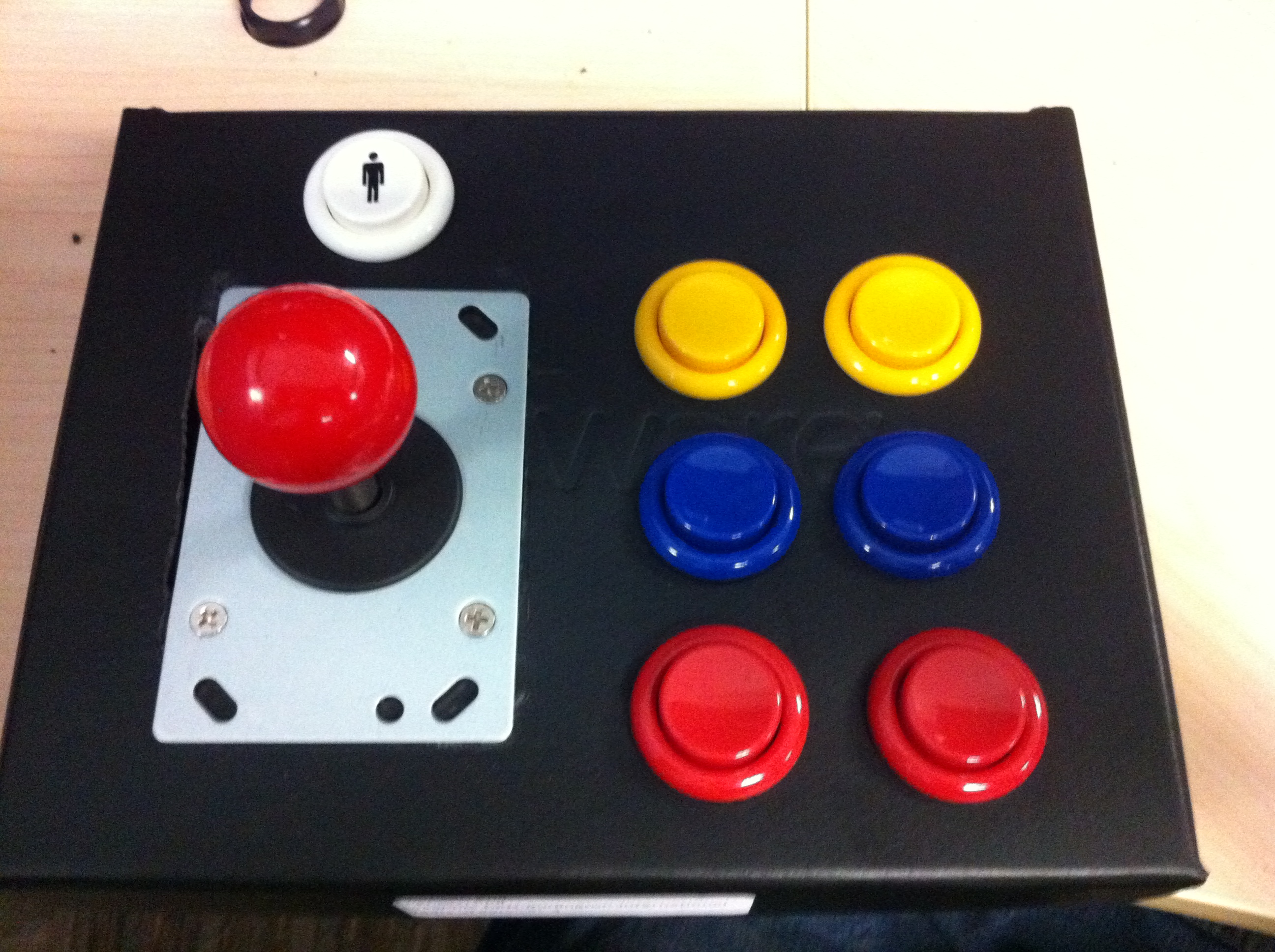
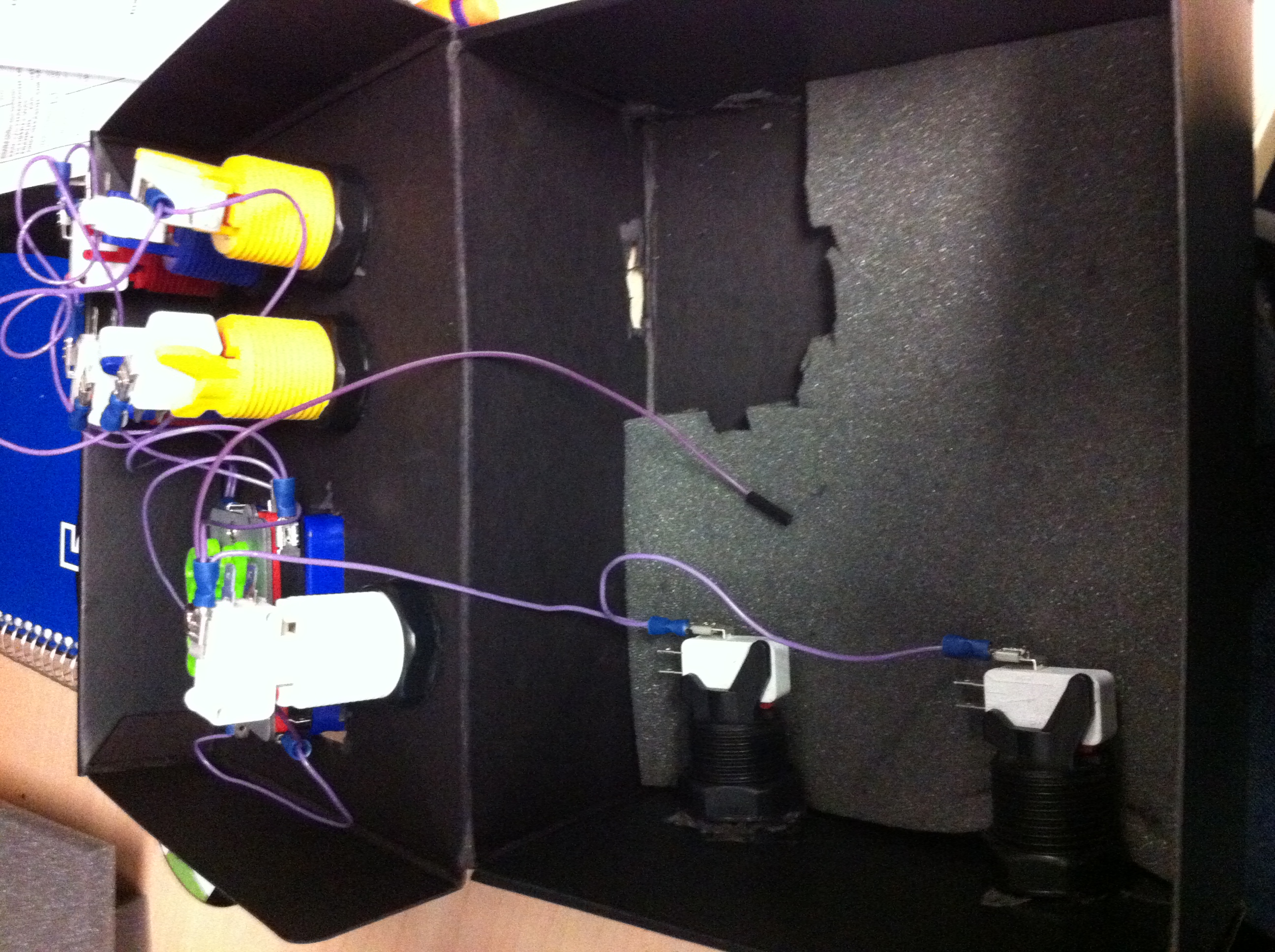
Well I got a sudden urge to replace it today and now I have a new shinier box with moar buttons, smaller form factor and proper non Japanese buttons.
A few months back after I made my initial blog posts I had ordered a new set of buttons and a joystick for my next project which was going to be a cabinet however things didn’t work out to the point where I could buy the necessary tools and materials to make that a reality and the parts just ended up sitting in my drawer for the last 3 months. My original controller while still functional was beginning to fold at the corners as I made fairly frequent use of it so I was beginning to really worry about how much longer it would last.
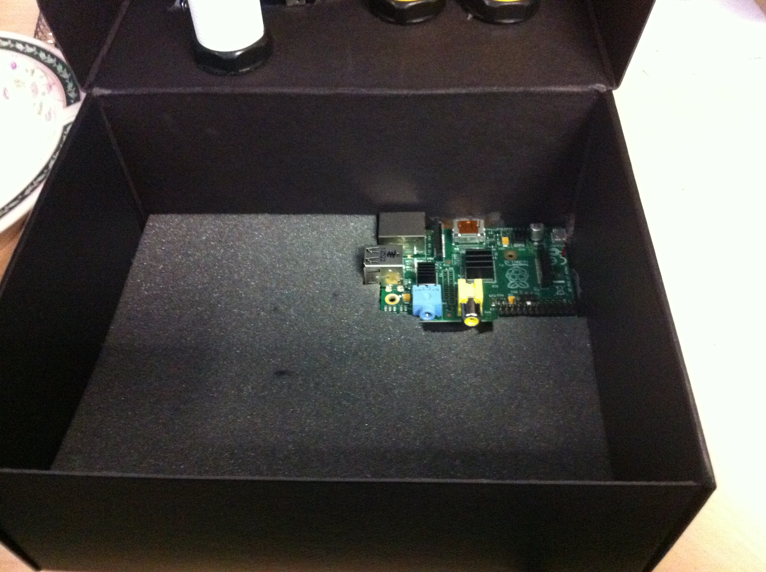
 That brings me to today, I was looking at a box on my desk from my 4 year service award and just like before the wheel began to turn and all of a sudden I was cutting out holes on the box for the stick and buttons. That was the easy part. I also decided months ago to get parts that would require traditional wiring so I had already made my ground line 3 months ago but I still needed to make my cables for the actual switches themselves. It wasn’t too hard, I had the tools and parts for that already from my initial purchase 3 months ago.
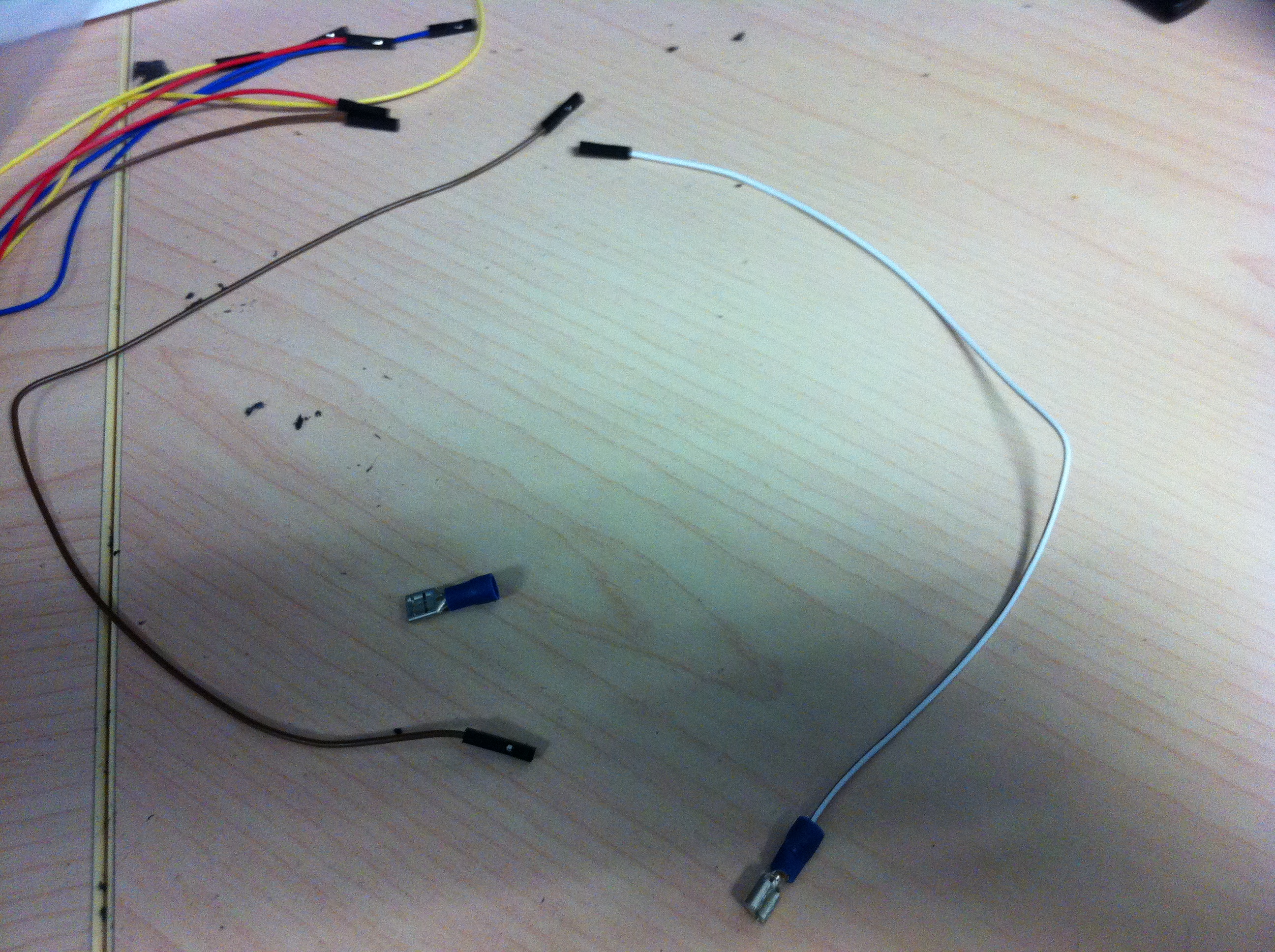
Creating the cables
I had a ribbon jumper cable kit from adafruit and I had a bag of crimp terminals from a local electronics store (.205 size fits perfectly). What I was doing was cutting the jumper off one end, stripping about 2 cm, turning the exposed wire downwards, placing the terminal over the wire/exposed wire and crimping it together. Blammo! one Joystick switch -> pi GPIO cable created. repeat 13 times.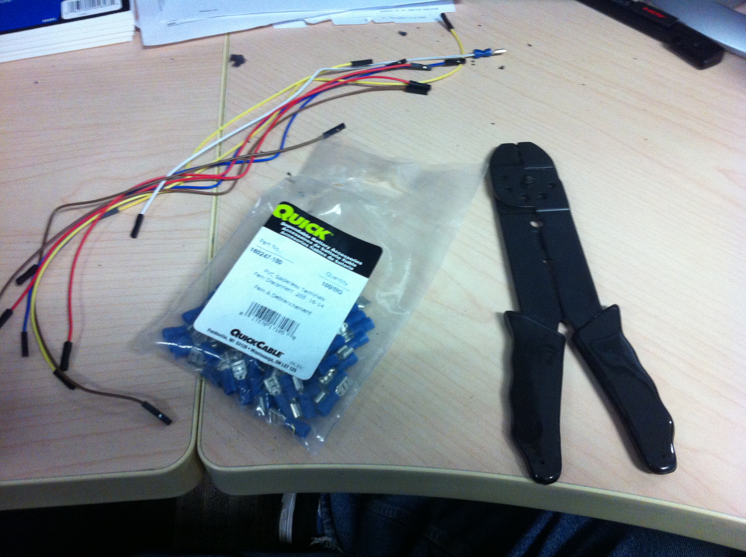
Once all the button cables were created I attached them to the Normal Open connector (NO) I already had the switches attached to a daisy chained ground cable I made months before and the jumper end to an open GPIO slot.
Setting up the OS
In my original box I was following an Adafruit tutorial that in the end gives you a retrogame.c file that gives you an easy way to map you controls to the GPIO, I continued with this program in this case as well. I had to add several more lines to the table since I was now supporting 6 play buttons and 1 more additional function button but the program is very straightforward to edit. I had to add KEY_SPACE,KEY_LEFTSHIFT,KEY_Z, KEY_X,KEY_ESC to the default table. I also had to make a small change to mame4all to remove the 1+coin escape workaround I had previously implemented.
What’s changed
- Well the obvious is 6 play buttons now instead of 2 but I also added an Escape button instead of having to do coin + 1p.
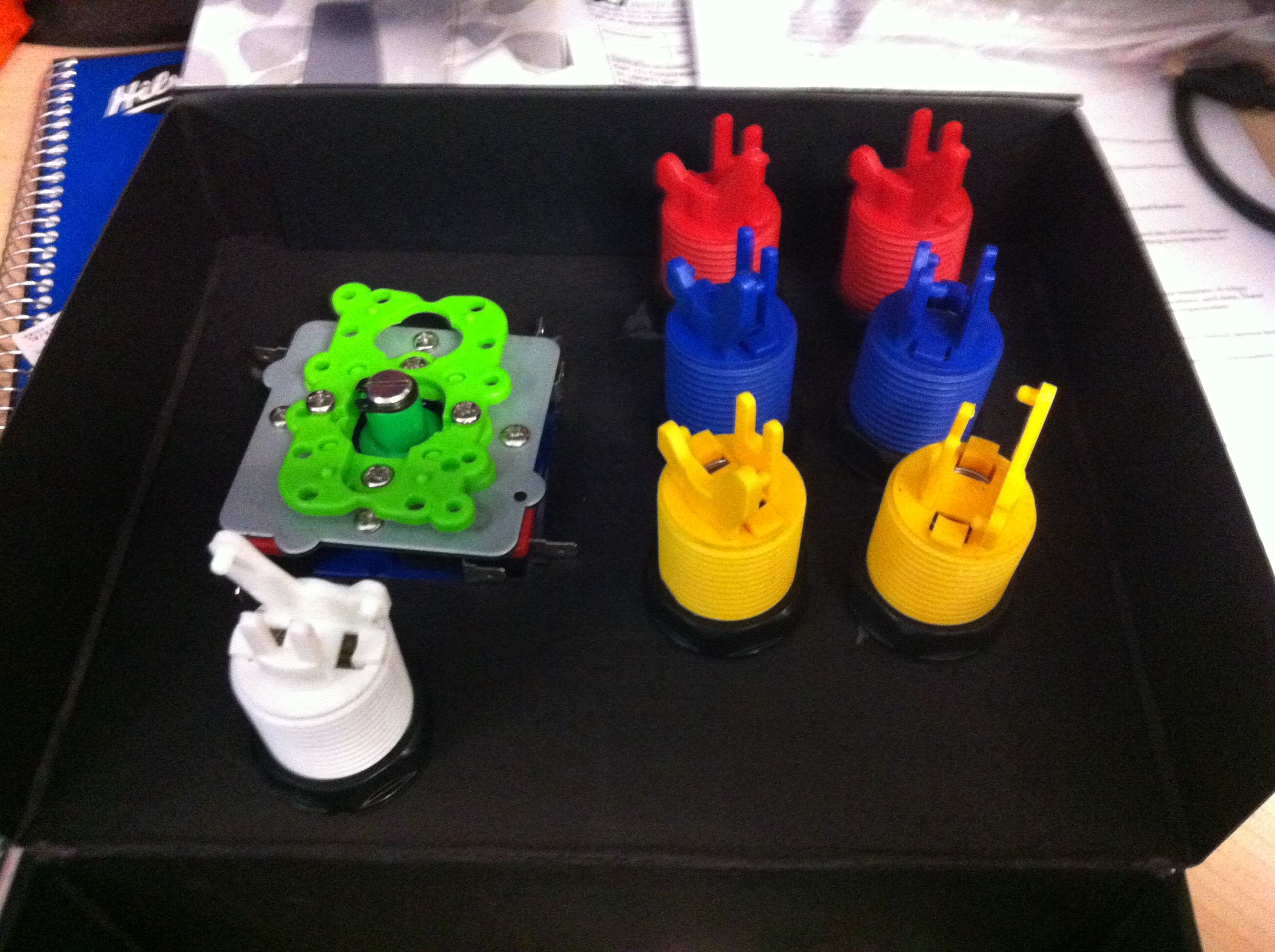
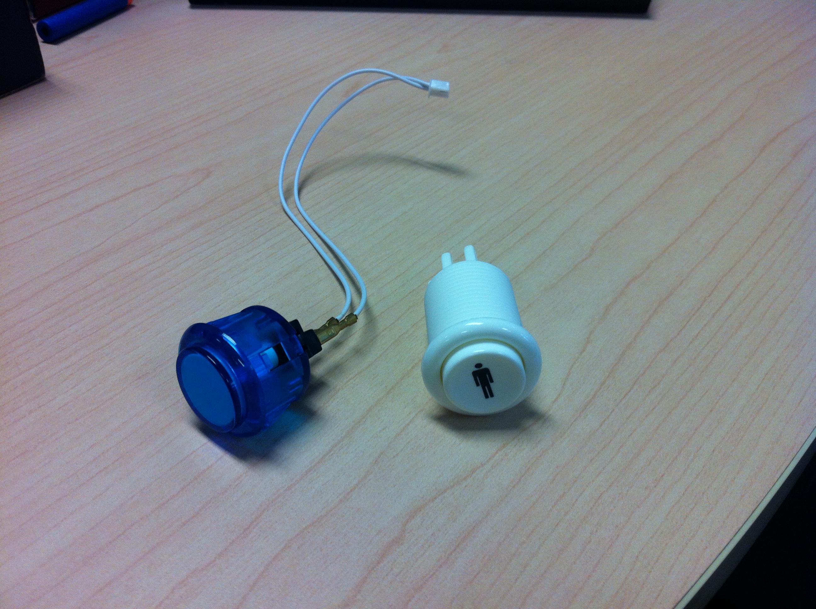
- No longer using Sanwa buttons, using the American style with the indented button.
- The size has also been reduced considerably.
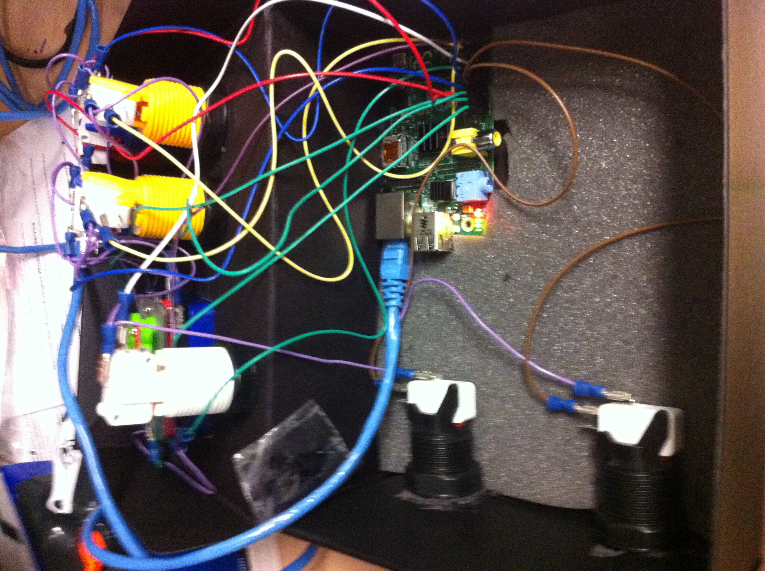
- The pi is more secured into place instead of just dangling about as before.
- The cut outs on the exterior are more matching to the ports being used (HDMI, power, SD card)
- Not as much ugly tape is visible, a small bit of 2 sided can be seen holding the stick in place
The long term plan is still to eventually make a cabinet but for now this will be more than enough to do the job.
[…] changes to my arcade emulator system. The last change of course being 2 years ago when I made a controller out of my 4 years service award box to replace my first shipping box arcade controller. It was time to build […]