popey had asked me for some more details a couple weeks ago regarding my Arcade console so here we are. I am going to post the GPIO layout similar to what I did with the old Arcade box and I will also post the changes I made to retrogame.c which takes the GPIO inputs and converts them to MAME keyboard input.
GPIO layout
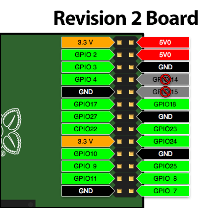
Similar to last time here is a standard Pi GPIO layout, the old controller layout and my current controllers layout. I matched most of the buttons wiring to their actual colour with a purple ground cable, green for the joystick wiring and the black buttons have brown wires.
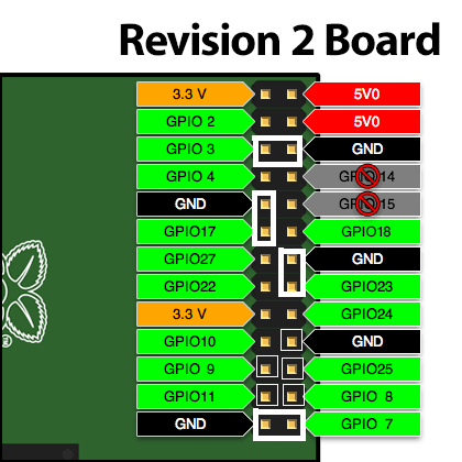
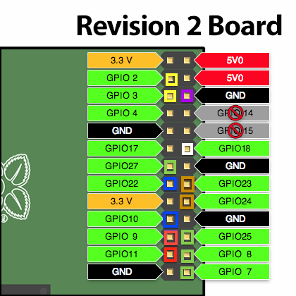
Notice that I only used one ground this time, I daisy chained the ground cable between all the buttons. This wasn’t possible last time because each button cable had a single wide jumper that straddled 2 pins so it needed to be laid out in a manner that was always next to a GND and that was limiting in my original design. In this new layout I still have 2 free GPIO pins I could use if needed.
retrogame.c
This file was provided by a tutorial on Adafruit and that is where the original box started with me doing their tutorial (with some slight improvements). For the new box it had to be expanded to cover all the buttons I was using and I am quite happy to report the Pi has no issue with rapid simultaneous input that can come from playing something like Street Fighter 2. Also, on my original post I said I had added an escape button but instead I went back to Coin + P1 for escape and made the additional side button into a pause. It has worked out significantly better this way.
The input table:
#define GND -1
struct {
        int pin;
        int key;
} io[] = {
//        Input    Output (from /usr/include/linux/input.h)
        { 8 ,      KEY_LEFT     },
        { 27,      KEY_RIGHT    },
        { 7 ,      KEY_UP       },
        { 25,      KEY_DOWN     },
        { 11,      KEY_LEFTCTRL },
        {  9,      KEY_LEFTALT  },
        { 24,      KEY_5        },
        { 18,      KEY_1        },
        { 10,      KEY_SPACE    },
        { 22,      KEY_LEFTSHIFT},
        { 2 ,      KEY_Z        },
        { 3 ,      KEY_X        },
        { 23,      KEY_P        }
};
#define IOLEN (sizeof(io) / sizeof(io[0])) // io[] table size
Simple stuff, { Pin # on the GPIO board, Key_Definition } (Thanks Adafruit!)
The full file can be viewed here: retrogame.c
The compiled file is run in the background on boot and takes the input on those pins and sends them as the specified key.
If there is any other aspect of the machine you want details on feel free to leave comment, most of the OS stuff was covered in the old consoles post. I used the same flash card for this one so it isn’t any different unless specified in the new consoles post or this one.
Facebook Comments